Mirror reflection and transmission
(An optics simulation, part of the Finesse examples)

The following shows a simple example for a Finesse simulation, including the text input file, a brief explanation and the resulting plot. This example has been used in the review article Interferometer Techniques for Gravitational-Wave Detection (see section 2) and is meant to introduce some of the syntax an use pattern of Finesse.
The input file
%------------------------------------------------------------------------
% Finesse input file to plot the mirror reflectance and transmittance
% Andreas Freise 15.08.2009
%------------------------------------------------------------------------

laser  l1 1 0 n1  % laser with P=1W at the default frequency
space  s1 1 n1 n2 % space of 1m length
mirror m1 0.5 0.5 0 n2 n3 % mirror with T=R=0.5 at zero tuning
ad ad_t 0 n3      % an `amplitude' detector for transmitted light
ad ad_r 0 n2      % an `amplitude' detector for reflected light
set t ad_t abs
set r ad_r abs
func total = $r^2 + $t^2 % computing the sum of the reflected and transmitted power

xaxis m1 t lin 0.5 0 100 % changing the transmittance of the mirror `m1'
yaxis abs:deg     % plotting amplitude and phase of the results
We use Finesse simply to plot the amplitudes of the light fields transmitted and reflected by a mirror (given by a single surface). The first three (non-comment) lines define the optical setup, the next two lines specify two detectors that produce output signals of the simulation and the last five lines contain commands to initialise and run the simulation.
The optical layout

The optical layout in this example is very simple: a laser emits a beam which propagates through free space and is then impinging on a mirror. The light is partly reflected and partly transmitted. In Finesse we can have `amplitude' detectors that can measure the field amplitude, a device that unfortunately does not have an equivalent in real optical experiments. Also, detectors in Finesse can measure the light without blocking it. This is here hinted at with the red dashed lines. (NB the illustration has been created with the free ComponentLibrary.)
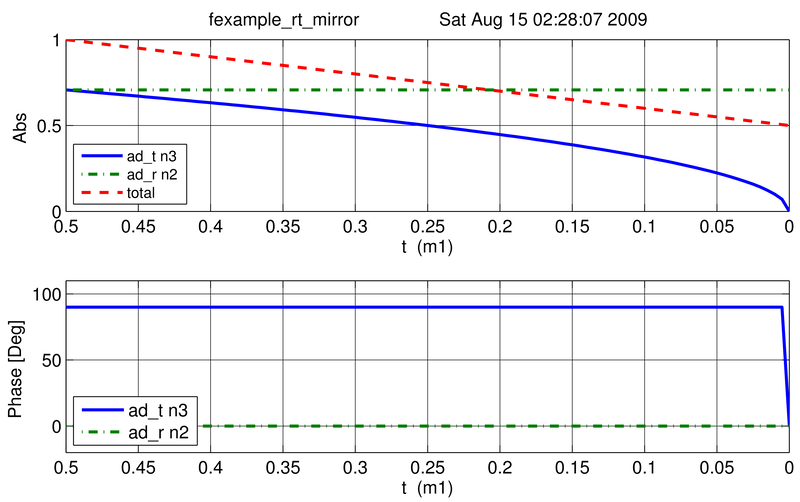
Output graphs
To run a Finesse simulation often means to plot a certain interferometer signal as a function of a parameter of the optical setup. Initially the mirror has a power reflectance and transmittance of R = T = 0.5 and is thus lossless. For the plot (see below) we tune the transmittance from 0.5 to 0. Since we do not explicitly change the reflectivity, R remains at 0.5 and the mirror loss increases instead, which is shown by the trace labelled `total' corresponding to the sum of the reflected and transmitted light power. The plot also show the phase convention of a 90 degrees phase shift for the transmitted light.