Length and tunings
(An optics simulation, part of the Finesse examples)

The following shows a simple example for a Finesse simulation, including the text input file, a brief explanation and the resulting plot. This example has been used in the review article Interferometer Techniques for Gravitational-Wave Detection (see section 2) and is meant to introduce some of the syntax an usage of Finesse.
The aim of this Finesse example is to demonstrate the difference between changing the length of a `space' component and changing the position (here called tuning) of a `mirror' or `beamsplitter' component. In Finesse the length of a space component is always defined as a multiple of the default wavelength (set in kat.ini). Small changes in the phase of the light propagating between two optics can be changed by changing the microscopic positions of mirrors or beamsplitters. This parameter, called `tuning' refers to a length change smaller or equal to the default wavelengths. Tunings are given in degrees with 360 deg referring to a change of one lambda. These conventions for lengths and microscopic positions are introduced in Section 3 of the Finesse manual.
The input file
%------------------------------------------------------------------------
% Finesse input file to plot the phase of light field reflected from a
% beam splitter to show the way lengths and positions are handled
% Andreas Freise 15.08.2009
%------------------------------------------------------------------------

laser  l1 1 0 n1    % laser with P=1W at the default frequency
space  s1 1 1 n1 n2 % space of 1m length
bs     b1 1 0 0 0 n2 n3 dump dump % beam splitter as `turning mirror'
space  s2 1 1 n3 n4 % another space of 1m length
ad     ad1 0 n4     % amplitude detector

% for the plot we perform two sequenctial runs of Finesse
% 1) first trace: change microscopic position of beamsplitter
xaxis b1 phi lin 0 180 100
% 2) second trace: change length of space s1
% xaxis s1 L lin 1 2 100

yaxis deg     % plotting the phase of the results
The setup consists of a laser beam being reflected from a beam splitter and then detected by an amplitude detector. The phase of the light field is plotted. Here in the first run, the tuning of the beamsplitter is changed from 0 to 180 deg, and in the second run the length of space component `s1' is changed from 1 to 2 meters.
The optical layout
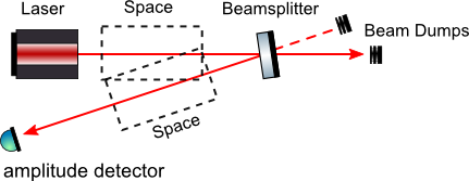
The optical layout in as follows: a laser emits a beam which propagates through free space and is then reflected from a beamsplitter, propagates through another free space and is detected by an amplitude detector. Two nodes of the `bs' component are labelled `dump' in the input file, which can be understood as beam dumps or beam blocks.
The beamsplitter here is drawn at an angle so that the reflected beam and the injected beam do not directly overlap. Note that this has been done to make the illustration clearer; the setup as defined by the input file has the beamsplitter being hit under normal incidence. (NB the illustration has been created with the free ComponentLibrary.)
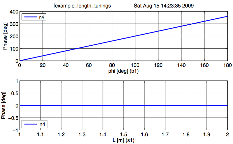
Output graphs
The Finesse output has been created in two sequential simulation runs. The resulting plots have been joined into the figure below. The top trace depicts the phase change of a beam reflected by a beam splitter as the function of the beam splitter tuning. By changing the tuning from 0 to 180 deg the beam splitter is moved forward and shortens the path length by one wavelength, which by convention increases the light phase by 360 deg. On the other hand, if a length of a space is changed, the phase of the transmitted light is unchanged (for light at the default wavelength) as shown the in the lower trace.