Cavity automatic alignment
(An optics simulation, part of the Finesse examples)

2012
The following shows a realistic example for a Finesse simulation, including the text input file, a brief explanation and the resulting plot. This example computes error signals for an auto-alignment system of a two-mirror cavity. It demonstrates the use of the `lock' feature in Finesse (to keep the cavity on resonance during the simulation).
The input file
%----------------------------------------------------------------------------------------------------------
% Finesse input file to compute the alignment signals generated from a
% cavity in reflection using the Ward technique
% Paul Fulda 17.02.2012
%----------------------------------------------------------------------------------------------------------

l laser 1 0 nin                          % Laser P=1W f_offset=0Hz
mod EOM 15M 0.001 1 pm nin n0            % Phase modulator f_mod=15MHz, modulation index=0.001
maxtem 3                                 % Include HG modes up to order 3
s s0 0 n0 n1
bs pickoff 0.1 0.9 0 45 n1 dump n2 n3    % Beam splitter with R=0.1, T=0.9 at zero tuning
s s1 0.1 n2 n4                           % Space 10cm length
m ITM 0.99 0.01 0 n4 n5                  % Cavity input mirror with R=0.99, T=0.01, at zero tuning
s scavity 1 n5 n6                        % Space 1m length
m ETM 0.99 0.01 0 n6 n7                  % Cavity end mirror with R=0.99, T=0.01, at zero tuning

s s2 0.1 n3 n8                           % Space 10cm length
bs bsQPD 0.5 0.5 0 45 n8 n9 n10 dump     % Beam splitter with R=T=0.5 at zero tuning
s sQPD1 0.1 n9 n11                       % Space 10cm length
s sQPD2 0.1 n10 n12                      % Space 10cm length

cav cavity ITM n5 ETM n6                 % Trace cavity eigenmode for the cavity (mirrors ITM and ETM)
trace 2                                  % Display results of cavity trace to terminal output
attr ETM Rc 1.3                          % Add curvature with radius 1.3m to mirror ETM
attr ETM xbeta 0                         % Add a variable for the angular tuning of mirror ETM
attr ITM xbeta 0                         % Add a variable for the angular tuning of mirror ITM
pd1 PDrefl 15M 0 n8*                     % Photodetector with demodulation at 15MHz, demodulation phase 0

attr sQPD1 g 40                          % Fix the Gouy phase shift the space QPDsplit2QPDrefl1 to 40 degrees
attr sQPD2 g 130                         % Add 90 deg Gouy phase shift to the space QPDsplit2QPDrefl2

pd1 QPDrefl1 15M 0 n11                   % Photodetector with demodulation at 15MHz, demod. phase 0 deg
pdtype QPDrefl1 x-split                  % Specify that QPDrefl1 is a split photodiode

pd1 QPDrefl2 15M 0 n12                   % Photodetector with demodulation at 15MHz, demod. phase 0 deg
pdtype QPDrefl2 x-split                  % Specify that QPDrefl2 is a split photodiode

set err PDrefl re                        % Define the signal from PDrefl to be used to generate error signal
lock z $err 3000 10n                     % Generate feedback signal, gain of 3000, lock accuracy of 10ppm
put ETM phi $z                           % Apply feedback signal to the tuning of mirror ETM
noplot z                                 % Don't plot the feedback signal
%xaxis ITM xbeta lin 0 0.8m 500          % Sweep misalignment of mirror ITM from 0 to 0.8mrad
xaxis ETM xbeta lin 0 0.8m 500           % Sweep misalignment of mirror ETM from 0 to 0.8mrad
The optical layout
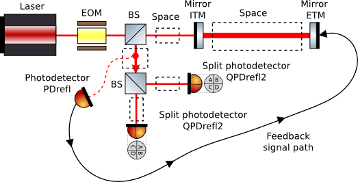
The illustration of the optical layout has been created with the free ComponentLibrary. It shows the optical components as well as the feedback path for the `lock' which is simply a Finesse-internal iteration which can be used to keep an optical system at its operating point. Please note that this does not simulate the actual control system!
This example demonstrates the generation of alignment control signals for a cavity using the Ward technique. The EOM adds phase modulation sidebands to the light from the laser at 15MHz. The light is then passed into the cavity. The reflected light from the cavity is picked off from the input light by the upper beam-splitter. Photodetector PDrefl measures the light reflected from the cavity with a demodulation frequency of 15MHz, thus generating a control signal for the length of the cavity in accordance with the Pound-Drever-Hall technique. This feedback signal is then applied to control the tuning of the cavity end mirror to keep it on resonance.
The reflected light from the cavity is also split by the lower beamsplitter to be measured at the two split photodetectors QPDrefl1 and QPDrefl2. At each split photodetector the difference signal between the left and right portion is demodulated at 15MHz. This gives as an output signal the beat between the light directly reflected from the cavity in the HG00 mode, and the light in the HG10 mode leaking out from the cavity as a consequence of misalignment of either of the cavity mirrors. This signal is therefore proportional to the misalignment of the cavity mirrors, making it an ideal error signal for alignment control. QPDrefl1 and QPDrefl2 observe the reflected light at Gouy phase quadratures different by 90 degrees. This gives QPDrefl1 and QPDrefl2 an different sensitivity to misalignments of the cavity end mirror and input mirror respectively, so that these degrees of freedom can be separated.
Output graphs
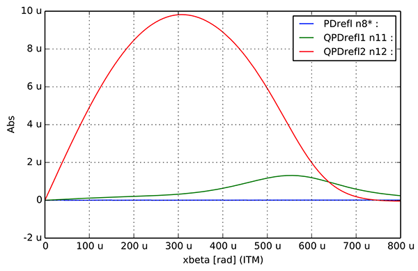
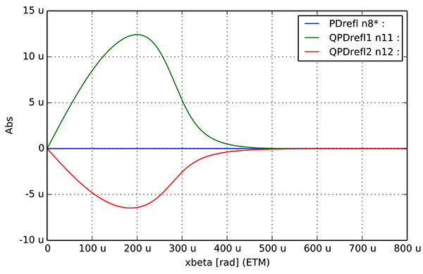
In each plot, the three traces show the signals from PDrefl, QPDrefl1 and QPDrefl2, as the alignments of either the cavity input mirror or end mirror are swept. When the input mirror's alignment is varied, the signal from QPDrefl2 has a steep slope around 0 degrees, and the signal from QPDrefl1 is almost flat. When the end mirror is mislaigned both detectors outputs have a steep slope but with a different sign. This shows that alignment signals from the cavity input and end mirror are well separated, and control loops using QPDrefl1 and QPDrefl2's signals can be used to optimise the alignment of the end mirror and input mirror respectively. Note that the signal from PDrefl is virtually zero at all alignment tunings: this is because the longitudinal control loop keeps the cavity on resonance even as the alignment is swept.
Only one graph will be plotted for each Finesse run - to plot both just swap between the commented and uncommented 'x-axis' lines at the bottom of the kat file.