Advanced LIGO and LG33 modes
(An optics simulation, part of the Finesse examples)

2012
The following shows a realistic example for a Finesse simulation, including the text input file, a brief explanation and the resulting plot. The example illustrates the effects of realistic Fabry-Perot cavities on higher-order Gaussian modes. In this example we model an Advanced LIGO arm cavity with an higher-order Laguerre-Gauss mode LG33 as the injected input mode. The cavity is modelled with a measured mirror map of the surface of an Advanced LIGO mirror substrate applied to the end mirror of the cavity to represent a realistic mirror surface. This illustrates the effects of realistic surfaces on higher-order modes such as LG33, highlighting the degeneracy and frequency splitting effects.
The input file
%--------------------------------------------------------------------------
% LG33_LIGO_cavity_scan.kat
%
% Finesse input file which computes the cavity scan of an Advanced LIGO
% style cavity simulated with an LG33 input beam over a range of finesse.
% An Advanced LIGO mirror map, ETM08, is applied to the ETM.
%
% 30.01.2013    Charlotte Bond
%--------------------------------------------------------------------------

% Input laser light (1 W)
l i1 1 0 0 nin

% Arbitrary distance to input mirror
s sNs 1 nin nITM1

% LG33 input mode
tem* i1 0 0 0 0
tem* i1 3 3 1 0

% by using 11 modes you can compute a result faster but with less accuracy
maxtem 11
% Include modes up to order 15 for the most accuracy
%maxtem 15

% Input mirror with T=0.014 (dummy value) and radius 0.168m
m mITM 0.986 0.014 0 nITM1 nITM2

% Cavity length 2802.9m
s sC 2802.9 nITM2 nETM1

% End mirror with R=1
m mETM 1 0 0 nETM1 nETM2            # HR coated surface

% ------------------- Comands for coupling coefficients -------------------

% HG00 accumulated phase from spaces is 0
phase 2

% defining input mirror aperture radius
attr mITM r_ap 0.168

% Filename for ITM coupling coefficients
knm mITM itm_coupling

% Save ITM coupling coefficients in binary form
conf mITM save_knm_binary 1

% defining end mirror aperture radius
attr mETM r_ap 0.168

% mirror map applied to ETM
% See below to download this file if you want to run this yourself.
% This map is computer generated but its features at
% spatial frequencues match those of a measured surface map
% of an uncoated Advanced LIGO mirror.
map mETM etm08_virtual.txt

% Filename for ETM coupling coefficients
knm mETM etm_coupling

% Use Riemann integration method here for faster calculation
conf mETM integration_method 1
% A more accurate integration method can be used but is much slower
% conf mETM integration_method 3

% ETM interpolation method is linear
conf mETM interpolation_method 2

% Save ETM coupling coefficients in binary form
conf mETM save_knm_binary 1
%--------------------------------------------------------------------------

% ITM Rc = 1934, ETM Rc = 2245m
attr mITM Rc -1934
attr mETM Rc 2245

% Compute and use cavity eigenmode
cav cav_mode mITM nITM2 mETM nETM1

% Detect power circulating inside the cavity
pd P_circ nETM1

% Define variable to represent the finesse of the cavity
variable finesse 20000

% Tune the cavity
xaxis mETM phi lin 93.5 95 1000

% Tune the finesse of the cavity
x2axis finesse phi lin 300 20000 300

% Calculate the reflectivity coefficient for the ITM from the current value
% of the finesse.  Here we include an offset of 1e-10 to overcome the
% error generated by finesse when the $x2 (and hence denominator) is 0
func ref = 1 + ( pi()^2 - sqrt( pi()^4 + 4*$x2^2*pi()^2 ))/(2*$x2^2+0.00000000001)

% Calculate the power reflectivity for the ITM
func R = $ref*$ref

% Calculate the transmission for the ITM
func T = 1.0-$R

% Update reflectivity and transmission of ITM
put mITM r $R
put mITM t $T

% Plot circulating power
yaxis log abs
Download the mirror map etm08_virtual.txt here if you want to run this simultion yourself. Note that the compuation takes several hours!
In this example we simulate the arm of a gravitational wave detector, which is effectively a two mirror cavity. As Finesse uses Hermite-Gauss (HG) modes internally, we can model the cavity response by injecting a sum of 9 HG modes whose sum is equivalent to an LG33 mode. A mirror surface map provided by the Advanced LIGO project is applied to the end mirror to model the small deviations of the mirror surface from a perfect spherecial shape. We then compute the steady-state solutions for different resonance conditions and output the power circulating in the cavity with a photodetector at the ETM.
The optical layout

In this simulation the input laser beam is of the form of the higher order mode LG33 instead of the fundamental mode, LG00, currently used in gravitational wave detectors. The LG33 mode has been proposed for use in gravitational wave detectors as a possible new technique to reduce the impact of the thermal noise of the test masses. A Finesse simulation campaign has been carried out on the performance of LG33 within the strict requirements for gravitational wave detectors. This simulation illustrates the degeneracy and frequency splitting effects of higher-order modes.
A cavity is on resonance when the circulating light field is interfering constructively round trip after round trip. Hermite- and Laguerre-Gauss modes are subject to an additional phase shift (compared to plane waves) as they propagate depending on the order of the mode. Thus a cavity is resonant for different order modes at different cavity settings of the cavity length (also called tunings), with modes of the same order being resonant for the same tuning. The LG33 mode is one of 10 modes of order 9. Therefore, multiple modes will be resonant for the same cavity tuning.
The cavity optics are not perfect, but feature miniture deviations from a perfectly spherical shape. We include so-called mirror maps in our simulations; these are data arrays representing the measured surface height of the mirror. The effect of these small imperfections is to couple a fraction of the light from the input mode into other spatial modes. Using an LG33 input mode we find that the presence of realsitic mirror surface data results in the presence of other order 9 modes inside the cavity. We also find that the resonant tuning is no longer exactly equal for the different modes of order 9, a phenomenon called `frequency splitting'. This is due to the different intensity distributions of the modes, which effectively average different surface heights of the mirror. This causes a small phase change, or a slightly different cavity length, for the different modes. In this example we illustrate how the presence of surface distortions results in frequency splitting for the LG33 mode and how increasing the finesse can result in separation of the order 9 resonance peaks.
Output graphs
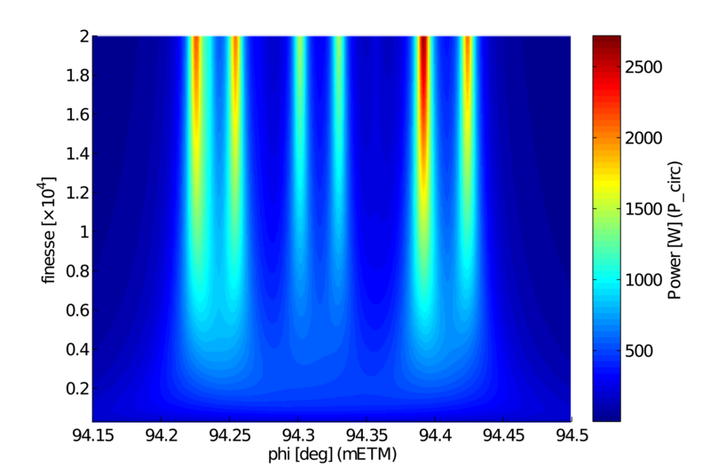
The plot below shows the power circulating in the cavity as the cavity is tuned and the finesse of the cavity is increased. The plot shows the region where the cavity is on resonance as the finesse is increased from 300 to 20000 (Advanced LIGO arm cavities have a design finesse of 450). We can clearly see that as the finesse of the cavity is increased the order 9 resonance peak splits into several distinct resonance peaks as the cavity line-width is reduced. These peaks correspond to the slightly different resonance peaks of different order 9 modes. In this case they correspond to the resonance peaks for different HG modes, as this particular mirror map has a significant astigmatic component. This breaks the vertical/ horizontal symmetry of the LG33 mode and effectively splits it into its composite HG modes. From left to right the 6 significant peaks correspond to HG90, HG63, HG45, HG36 , HG18 and HG09.